OPEN CIRCUIT TEST
It is also called no load test of Transformer.Used for finding iron or core losses of Transformer.
High voltage side of transformer is left open circuited and voltmeter is connected across it.This fig. shows the connection diagram for open circuit test.
Voltmeter, ammeter and wattmeter are connected to the low voltage side of transformer.
LV side of transformer is supplied at rated voltage and frequency and voltmeter on LV side reads the rated voltage "V1". since the secondary side is open circuited and hence very low current called no load current "Io" flows in the primary side and thus ammeter reads the no load current.
power loss in transformer is only due to core losses because copper losses are negligible. there are no copper losses in secondary since it is open and no load current on the primary side is very very small.
Thus wattmeter only reads the power loss due to core losses.
SHORT CIRCUIT TEST
Also called impedance test of Transformer.
Used for finding copper losses in transformer.
 |
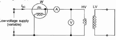
| SHORT CIRCUIT TEST OF TRANSFORMER |
LV side of transformer is short-circuited by thick copper conductor. Given fig. shows the circuit diagram for short circuit test.
Ammeter, voltmeter and wattmeter are connected on HV side of transformer.
HV side is supplied reduced voltage from variable voltage supply.
Since the HV side is supplied at reduced voltage and supply voltage is varied until full load primary current flows. voltmeter reads the primary applied voltage since the voltage is very low and hence flux produced is also very low.
Core losses are directly proportional to the square of flux and hence core losses becomes low and it can be neglected. So, Wattmeter only reads the power loss due to copper loss since full load current are flowing.
Thanks for reading.
Keep Sharing & loving.
Keep Sharing & loving.
