Main objective of the Sumper's test is to check the transformer efficiency , maximum temperature rise. It is also used to measure the losses in the large transformers. This method is advantageous for large transformers because for full load test on large transformers, it would be expensive as a large amount of energy will get wasted during the test. Therefore, large transformers can be tested by SUMPNER'S TEST.
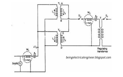
Sumpners test requires requires two identical transformers. Given figure shows the circuit diagram for back-to-back test (Sumpner's test).
The primary winding of the two transformers are connected in parallel and is supplied at rated voltage and frequency. As seen in the figure, a Voltmeter, an ammeter and wattmeter are connected to the input.
The secondary of the transformers are connected in series in phase opposition and voltmeter is connected across them. The range of the voltmeter is twice the voltage of secondary winding. Phase opposition of the winding is checked by this voltmeter. If voltmeter reads 0, it means they are in phase opposition , because both windings have equal voltages but in opposite direction due to which overall voltage in the secondary circuit become 0.
Now if the supply is given to the primary circuit, then the total voltage in secondary circuit will be 0, as discussed above.
There will be no current in the secondary winding and it will behave as secondary is open circuited. Only No-load current will flow in the primary circuit which is measured by the ammeter on the primary side.
Hence , wattmeter on the primary side will read the total Iron losses of the both transformers.
Now, a small voltage is injected in the secondary circuit with the help of regulating transformer (see the figure). The magnitude of the voltage is adjusted till the ammeter on the secondary side reads the full-load secondary current. This produces the full load copper losses of the both transformers. Thus wattmeter on the secondary side reads the total Full-load copper losses.
Thus with the help of this method we have founded the both losses in the transformer. We have loaded the transformer to the full load but the power taken from the supply is just that it will be only sufficient to supply the losses of both transformers.
